Who is Ollie?
Ollie from Pritika Nilaratna on Vimeo.
Abstract
Ollie is a blimp-based autonomous and ambient robot that dwells in human habitats. Ollie is equipped to demonstrate humor and patterns of delicate emotions. Ollie is observant, often flying in a manner suggesting curiosity for the world around him. Ollie reacts to voices by excitedly flapping his wings, communicating his friendliness and eagerness to be noticed. Ollie is often socially awkward and unobtrusive. Ollie wants to know about humans and yearns for their attention. Ollie is a performer.
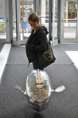
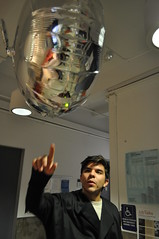
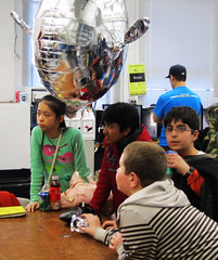
Robotics increasingly pervade our everyday lives. Machine-human interaction has the potential to be both poetic and ubiquitous. Ollie, the autonomous robotic blimp, is a demonstration of the creative capabilities of robots as inhabitants of our society, breaking the stereotype of the servile robot. The technology behind Ollie is open source and available to artists, Do-it-yourself enthusiasts and students under Creative Commons Attribution-ShareAlike 3.0 Unported License to further encourage creative computing and collaboration.

Artist
Ollie is developed by Pritika Nilaratna.
Pritika Nilaratna is a creative technologist and interaction designer based in New York City. She graduated with BFA in Design & Technology at Parsons The New School for Design. Nilaratna’s work as a designer is motivated by humor, critique and social intervention in and through technology. She enjoys web and mobile user experience, interactive design installations and glistening, brilliant blue jewels.

Instructions for making Ollie
Ollie is a DIY autonomous robotic blimp who is vulnerable, socially awkward and yearns for attention. Ollie has wings that allow him to fly and a microphone that allows him to listen. In this tutorial I will teach you how to make Ollie so you can meet him too.
You may also read my instructable here.
Please contribute suggestions, experiments, tweaks, hacks and discoveries of your own process. Thank you!
Jump to these links at anytime:
Part-1 Making the Wings
Part-2 Adding Micriphone and LED
Part-3 Tips for Pro Users
The main parts needed are :
- 1 Arduino Pro Mini 328 – 5V/16 Mhz
- 1 FTDI cable or breakout board to charge Arduino Pro Mini
- 1 Electret Microphone
- 1 Polymer Lithium Ion Battery 850 – 900 mAh
- 2 Blue Arrow 3.6 Gram Micro Servos
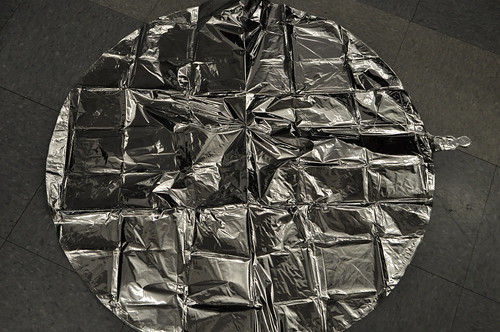
- 1 36″ Mylar balloon envelope
- 1 30 guage wire/ wire-wrapping wire in 2-3 colors
- 1 LED
- 1 Sheet of Mylar or foil for wings
- 1 Spool of sculpture wire for wings
- 1 Helium tank or access to a party store
- 1 Switch
- 1 3.9 KΩ resistor
- 1 4.7 KΩ resistor
Additional items
- Arduino Uno or other (for testing)
- Breadboard
- 22 or 24 guage wire
- Lightweight tape
- Small weighing scale
- Soldering iron and solder
- Quick-setting Epoxy
- Glue gun
- Playdoh or clay
- Small cups
- Cutter
- Wire stripper
- Wire wrapping tool
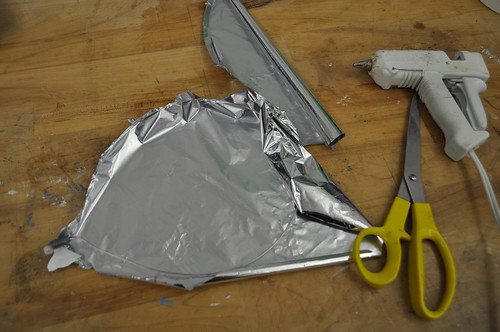
Making the Wings
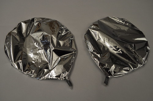
- Bend sculpture wire to create 2 identical wing shapes. Try to conserve amount of wire used to minimize weight. Use epoxy to secure the ends.
- Attach servo accessory to the ends of the wings keeping check of orientation and secure with epoxy. Secure with small pieces of tape if necessary.
- Cut out identical pieces of Mylar or foil and attach to wire shapes using a glue gun. Leave the foil loose when attaching so it takes a hemispherical shape when wing is flapped.
- Attach wings to the servo.
- Wire up the servos using wire-wrapping wire.
- Plug the control wires from the servos to digital pins 2 and 4 and connect to 5V power and ground on a breadboard and/or Arduino Uno (for testing)
- Upload a basic servo program to check wiring making sure that both wings exhibit identical motion.
- If wings are not moving check continuity in circuit, secure connections and try again. If circuit works, disconnect and prepare wiring for Arduino Mini Pro.
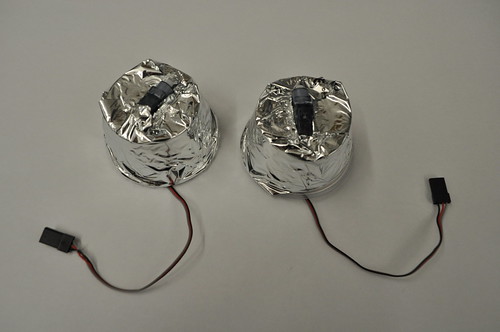
- Insert servos through 2 small identical plastic cups and glue to secure in place. Make sure wings move without any obstructions. Cups are useful in attaching wings to the balloon and hiding wires.
- Mark points on the empty 36″ blimp envelope where wings will be mounted. Points should be in exactly opposite on the balloon surface and provide balance to the blimp.
- Cover the cups with Mylar foil using glue gun.
- Fill up 36″ Mylar envelope with Helium.
- Attach servo cups to the balloon using small pieces of tape. Let wires hang loose.
- Cover the tape with pieces of Mylar or foil.

Adding Microphone and LED
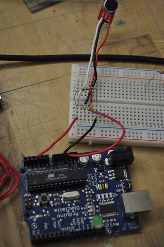
- Power the Electret mic through Arduino Uno as shown in circuit diagram using 2 resistors of 3.9Kohm and 4.7Kohm. Control wire should be plugged into analog pin 2 of Arduino.
- Connect LED to digital pin 13 on Arduino Uno.
- Make sure all connections are secure.
- Resistors are used to increase the amplification of the signal received from the Electret mic and should be wired correctly.
- Run this simple program to make sure input is being received. LED will light up whenever a certain threshold of volume is reached. This threshold should be set to a normal or loud talking volume.
- If the circuit is not working play with the values in the program and make sure resistors are wired correctly.
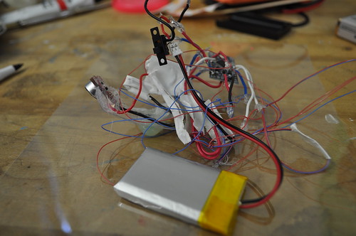
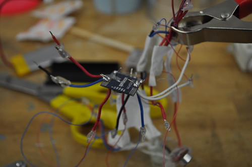
- If the circuit works, wire everything up according to the circuit diagram. Attach toggle switch and LiPo battery to the circuit. Solder all the wires directly to each other and secure with hot glue.
- Upload the final Arduino sketch given below to the Pro Mini using FTDI cable or breakout board.
- Solder connections to the Arduino Pro Mini very carefully according to the circuit diagram.
- Attach circuit to bottom of balloon using small amount of foil or tape.
- At this point circuit will be light enough to be lifted by the balloon or just the right weight to keep it in equilibrium. Adjust with a small amount of clay if circuit is too light.
- Ollie is ready to fly. Turn the switch on so Arduino Pro Mini is powered with the battery. Ollie will flap his wings whenever he hears you talk or a loud sound is made. Ollie will randomly burst into flight and bring happiness and joy in the life of many.
Tips for Pro Users
- Everything adds weight, so be frugal with materials. Total weight of materials mounted on blimp should always be monitored. This can be done by measuring with Playdoh or clay to see how much weight blimp can lift. Make sure electronics and circuit do not exceed this weight.
- If LiPo battery 900mAh is unavailable, replacement battery should be ~18.5g (0.65oz) or less.
- Helium runs out of Mylar slowly, Ollie will fly for at least 1.5-2 days before it needs refilling.
- Check entire circuit on breadboard or Arduino Uno before wiring or soldering to the Arduino Pro Mini.
- Be very, very careful while soldering to Arduino Pro Mini, the chip can get burned easily.
- Test servos and make sure wings are oriented correctly and moving in mirrored direction.
- Make adjustments to the code as is fitting to your environment.
- Submit your experiments, tweaks, hacks and suggestions to me. Ollie loves his cousins very much.

int buffer = 0;
//Sound variables
int potPin = 1;    // select the input pin for sound sensor
int ledPin = 13;   // select the pin for the LED
int soundVal = 0;
void setup()
{
  pinMode(ledPin, OUTPUT);  // declare the ledPin as an OUTPUT
  Serial.begin(9600);      // open the serial port at 9600 bps:
}
void loop()
{
    //Sound
    soundVal = analogRead(potPin);
    //Serial.println("Listening............");
    if( soundVal>1020 ){
      Serial.println("VERY LOUD!");
      digitalWrite(ledPin,HIGH);
     }
    else if (soundVal<450 || soundVal >750){
      if (buffer == 0){
        Serial.println(soundVal);
         buffer = 15;
         digitalWrite(ledPin,HIGH);
      }else{
         buffer--;
      }
    }
    else{
       digitalWrite(ledPin,LOW);
     }
}
#include <SoftwareServo.h>
SoftwareServo myservo;  // create servo object to control a servo
SoftwareServo myservo2;
int goUp = 0;
int val = 0;
int wait = 0;
int flyFor = 0;
long flapTime = 0;
int angleMin = 0;
int angleMax = 120;
int upSpeed = 20;
int downSpeed = 1;
int buffer = 0;
//Sound variables
int potPin = 1;    // select the input pin for sound sensor
int ledPin = 13;   // select the pin for the LED
int soundVal = 0;
void setup()
{
  pinMode(ledPin, OUTPUT);  // declare the ledPin as an OUTPUT
  myservo.attach(2);  // attaches the servo on pin 2
  myservo2.attach(4);
  Serial.begin(9600);      // open the serial port at 9600 bps:
}
void loop()
{
  // Servo
  if (flyFor < flapTime){
    if (wait == 5){
      if (val < angleMin){
        goUp = 1;
        digitalWrite(ledPin,HIGH);
        }
      else if (val >angleMax){
        goUp = 0;
        digitalWrite(ledPin,LOW);
      }
      if (goUp == 0){
        val-=upSpeed;
      }else {
        val+=downSpeed;
      }
    }
    wait++;
    if (wait > 200)
      wait = 0;
    myservo.write(val);
// sets the servo position according to the scaled value
    myservo2.write(120-val);
    SoftwareServo::refresh();
    flyFor++;
  }else{
     //Sound
    soundVal = analogRead(potPin);
    Serial.println("Listening............");
    if( soundVal>1020 ){
      Serial.println("FREEAK OUT!");
      upSpeed = 15;
      downSpeed = 15;
      angleMax = 45;
      angleMin = 10;
      flapTime = 6000;
   }
    else if (soundVal<450 || soundVal >750){
      if (buffer == 0){
        Serial.println(soundVal);
        upSpeed = random (1, 20); //1 to 30
        downSpeed = random (1, 30);// 1 to 30
        angleMax = random (110, 120);
        angleMin = random (30, 45);
        flapTime = 10000 + random (5000 , 10000);
        flyFor = 0;
        buffer = 15;
      }else{
         buffer--;
      }
    }
  }
}

'Fun Design and Toy > Interesting Device Design' 카테고리의 다른 글
| A Swarm of Nano Quadrotors (0) | 2012.02.03 |
|---|---|
| Quadcopter !!!! (0) | 2012.01.10 |
| Disco Droid - Android ADK Project (0) | 2011.07.21 |


